





1 实验材料与方法
1.1 实验材料
1.2 实验方法
2 结果与分析
2.1 组织结构
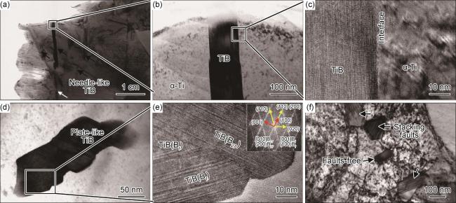
图 4 增材制造TiB/Ti复合材料微观组织TEM分析(a),(b)TiB晶须的明场相;(c)界面高分辨图;(d)盘片状TiB;(e)盘片状TiB的高分辨图和傅里叶变换图谱所示的[010]B27//[001]Bf和(200)B27//(110)Bf取向关系;(f)TiB的横截面 Fig.4 TEM analysis of additive manufactured TiB/Ti composites (a), (b)bright-field images of the nano-sized TiB whisker; (c)high-resolution image of the TiB-Ti interface; (d)plate-like TiB; (e)HRTEM image of the plate-like TiB and the corresponding fast Fourier transform (FFT) pattern indicating [010]B27//[001]Bf and (200)B27//(110)Bf; (f)cross-section view of TiB |
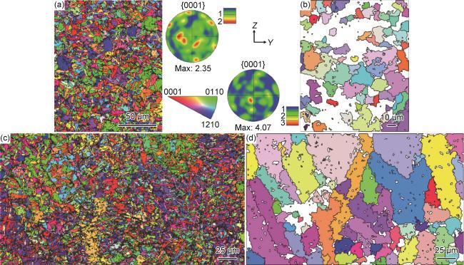
图 5 增材制造TiB/Ti复合材料EBSD分析(a)等轴网状区域的IPF图、{0001}PF图;(b)等轴网状区域重构的初生β晶粒IPF图;(c)柱状树枝网状区域的IPF图;(d)柱状树技网状区域重构的初生β晶粒IPF图 Fig.5 EBSD images of additive manufactured TiB/Ti composite (a)IPF maps, {0001}PFs of equiaxed network structure; (b)reconstructed β phase maps of the equiaxed network structure; (c)IPF maps, {0001}PFs of columnar dendritic structure; (d)reconstructed β phase maps of the columnar dendritic structure |
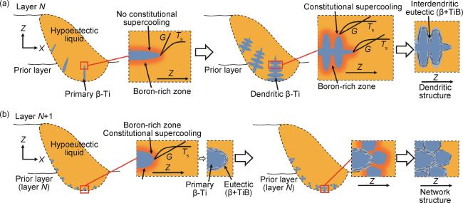
2.2 初生β晶等轴化与TiB网状形成机理
2.3 力学性能与原位拉伸表征
2.3.1 拉伸性能
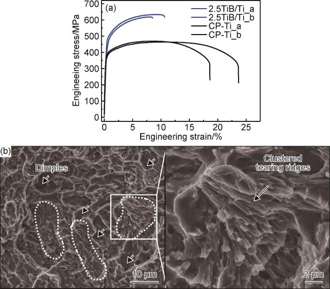
图 7 TiB/Ti复合材料的工程应力-应变曲线(a)与断口形貌(b)Fig.7 Engineering stress-strain curves(a) and fracture morphologies(b) of the composites |
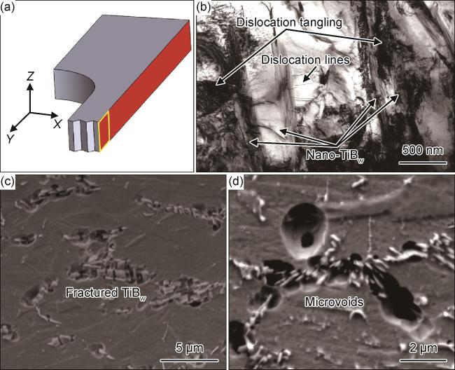
图 8 TiB/Ti复合材料拉伸断口侧面(ZOY面)组织结构(a)断口观察位置;(b)TiB晶须附近高密度位错;(c)平行于拉伸方向的TiB晶须;(d)垂直于拉伸方向的TiB晶须 Fig.8 Microstructure nearby the tensile fracture surface (ZOY section) of the TiB/Ti composites (a)observation point of the fracture; (b)high density dislocation around the TiB whiskers; (c)TiB whiskers parallel to the tensile direction; (d)TiB whiskers perpendicular to the tensile direction |
2.3.2 原位拉伸分析TiB网状结构对拉伸性能的影响
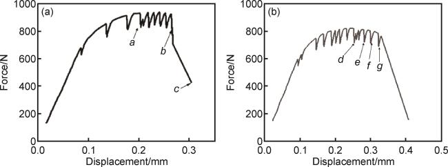
图 9 TiB/Ti复合材料原位拉伸曲线(a)试样1;(b)试样2 Fig.9 In-situ tensile curves of TiB/Ti composites (a)sample 1;(b)sample 2 |
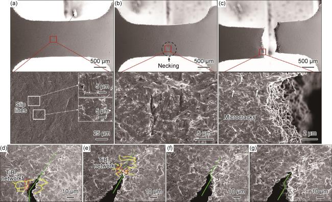


图 10 增材制造TiB/Ti复合材料原位拉伸微观组织演化分析(a)~(c)图 9(a)停驻位置a,b和c微观组织;(d)~(g)图 9(b)停驻位置d~g微观组织 Fig.10 Microstructural evolution of the in-situ tensile process of LMPed TiB/Ti composites (a)-(c)microstructural features at the test position of a-c in fig. 9(a); (d)-(g)microstructural features at the test position of d-g in fig. 9(b) |